
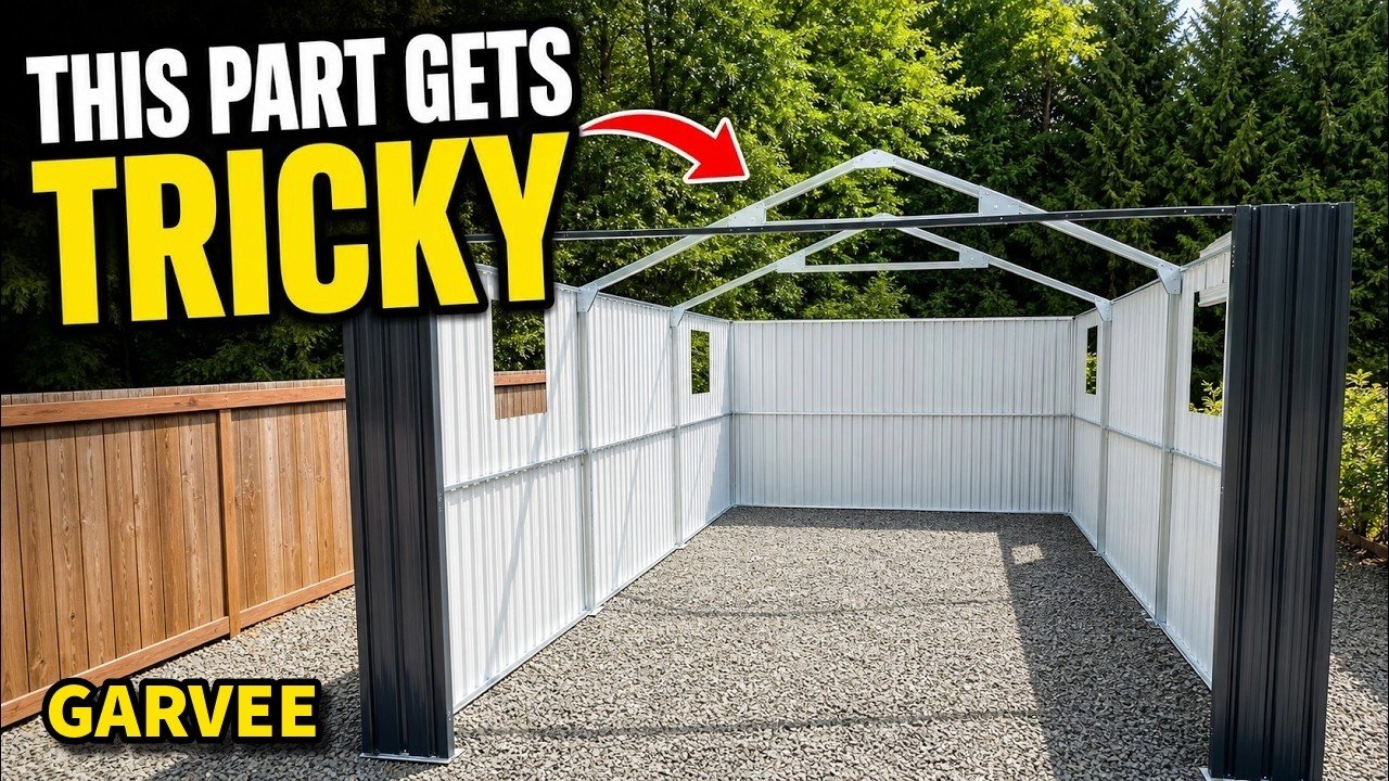
My GarveeLife 12×20 metal carport assembly involved much more than fastening panels to a frame. The finished enclosed shed gives me useful vehicle and storage space, but getting there meant sorting six boxes of parts, correcting my foundation plan, and peeling far more protective film than I expected.
Follow the build through 12 stages below. Each one includes a video timestamp so you can see how the parts came together.
Watch the complete Garvee metal shed build
Before you start
Use this guide alongside the instructions for your exact kit. Part numbers below refer to my build; versions can differ. Garvee’s installation notes for its enclosed metal garage call for a suitable level foundation, surface-appropriate anchors, and multiple adults for assembly. Confirm your model’s requirements and the building and wind-load requirements for your location.
- Have the manual, labeled hardware, drill/driver with matching bits, hand tools, measuring tape, level, clamps, and suitable ladders ready.
- Wear work gloves and eye protection. Metal edges are sharp, and large panels are awkward to handle.
- Arrange helpers before the lifting stages. We used two people for the trusses and three for the upper assembly. Follow your kit’s crew requirements.
- Choose calm conditions for raising the frame and handling panels. Use stable access equipment for roof work; do not treat the sheet-metal roof as a standing platform.
One fastening rule for the whole build: start the bolts by hand, get every hole in the assembly aligned, and then tighten evenly as directed by the manual. Fully tightening the first connection can pull the remaining holes out of position.
Jump to: Site · Base · Trusses · Walls · Windows · Roof · Doors
Step 1: Settle the foundation and anchoring plan
Prepare a flat, level installation area with room to work around the shed. Decide on the final base height, vehicle approach, door clearance, and anchoring method before assembling the frame.
I initially considered a raised cinder-block base, then removed the blocks because I did not want to fill the entire area or build a ramp. Keeping my build at ground level preserved the approach and door clearance. That change was specific to my site, not a foundation recommendation for every installation.
My instructions showed M10 anchors for concrete. A different surface needs its own suitable anchoring solution; skipping concrete anchors does not remove the need to anchor the structure. Resolve that requirement before proceeding.
Step 2: Sort the parts and remove protective film
Unpack all cartons and compare their contents with the parts list. My kit arrived in five long boxes and one shorter box. Group framing members, panels, and hardware by number and size, leaving enough space to read the labels.
Peel protective film before fitting a panel whenever possible. This was the biggest time surprise: some sheets took me 20–30 minutes each. Set aside real time for that job rather than treating it as a quick final cleanup.
Step 3: Dry-fit and square the base frame
Lay out the base sections before fastening them. Confirm the corners, center joints, and downward-facing flanges. In my kit, the rear center joint uses matching left and right pieces with connector 4D; the corners use H brackets.
Join the perimeter using the hardware shown in the manual. Check the base with a level and compare corner-to-corner diagonal measurements as you adjust it square. Tighten the connections evenly after the entire rectangle is aligned. This is the reference for the walls and door opening, so fix errors here before building upward.
Step 4: Assemble both roof trusses on the ground
Build the two trusses before lifting either one. The main pieces in my kit are A6/A7 and A1/A2. Follow the UP and DOWN stickers so the peak and mounting holes face correctly.
The A5 pieces sandwich the center section with their flanges outward, leaving the roof-panel mounting holes accessible. Add the A3/A4 side supports in the correct mirrored positions, then attach the lower 4T piece. Finish the second truss the same way and stage both safely for lifting.
Step 5: Build the rear support assembly
Fit the rear vertical support and assemble the 8L/8R crossmember with connector 10. The OUTSIDE labels identify the faces, and the connector’s specified orientation matters. Add the D/E end brackets, the curved W8 rear corner panel, and the first W3 wall panels as shown in the kit instructions.
One part in my build lacked the holes I expected. Before modifying a part, check its number and orientation, compare its matching partner, and contact the manufacturer if the discrepancy remains. Do not drill structural members just to force a connection that may be assembled incorrectly.
Step 6: Raise the trusses and complete the main frame
With helpers supporting the assembly, seat the first truss in the base and secure its legs using the specified fasteners. Install the connecting member and bracing required for that stage before moving on. The first standing truss had very little lateral support in my build; do not leave a partially erected frame unsupported.
Add the P7 horizontal member, raise the second truss, and connect the remaining P7 member. Then fit the front vertical supports and DN brackets. Assemble the wide front header on the ground from the matching 8-series sections and overlapping 23 channel before lifting it into place.
Finish the curved front corner panels and the 13A/13B brace run. Check the front/back markings where a brace shares a connection with another bracket. The frame should be aligned and securely braced before you begin cladding it.
Step 7: Install the wall panels in sequence
Use this method for each wall: position the next panel with the specified overlap, start its top and bottom screws, check that it is vertical, then complete the remaining fasteners. Leave the shared edge hole available until the adjoining sheet is in position.
Fit the supplied sealing washers on exterior panel fasteners wherever the manual specifies them. These washers help seal the holes around the fasteners. Seat them correctly without crushing them through overtightening.
Build the window openings from their left, right, upper, and lower panel sections. Check their arrangement against the wall layout before continuing the run. My back wall used nine W3 panels, followed by the matching side trim. Keeping the first panels straight prevents a small lean from growing across the wall.
Step 8: Fit the four windows
Identify the lower frame lip and orientation marks. Remove the film from the clear panel and seat it in its groove. I temporarily took the panel back out while attaching the frame so it would not slip during handling.
Reposition the clear panel and fit the inside frame section to sandwich it in place. A helper pressing from outside made it easier to bring the sections together. Work around the perimeter gradually, keeping the panel seated and avoiding excessive pressure on it. Apply the same procedure to the other three windows.
Step 9: Install the upper frame and roof supports
Assemble the upper front and rear sections on the ground. My build uses 21B/21D, the 30-series end pieces, and 11L/11R with connector 10. Follow the drawings and labels for the connector face.
We used three people to lift and secure the upper assembly: one holding position, one fastening, and one passing hardware and helping with alignment. Add the center beam from the 9/9F sections, followed by the 25/26 roof supports. Check their channel orientation and connections before covering them with roof panels.
Step 10: Fit the roof panels and ridge caps
Start the W12 roof panels at the front and work toward the rear, keeping both slopes at roughly the same stage. This lets you compare alignment at the ridge instead of finishing an entire side before discovering a mismatch.
On my build, I added the first piece-18 ridge cap after six panels were installed on each slope, then overlapped the next cap as the roof progressed. Follow your kit’s specified panel and cap overlaps. Use the required sealing washers at roof penetrations and check that each panel sits correctly against its supports.
Inspect the completed roof connections and seals before moving on. A covered structure is not proof of a watertight roof; check for leaks after rain and correct any issues using the manufacturer’s sealing guidance.
Step 11: Assemble and hang the doors
Lay out the door sections, hinges, latches, corner brackets, and washers in the order shown by the manual. My door sections begin with four D2 panels, framed by 17/17F side pieces and 22B top and bottom pieces. Add the reinforcing bars and hinges after the perimeter is assembled.
Have a helper support each door while you align its hinges. I used clamps to keep panels from swinging in the breeze and striking the shed. Start the fasteners, check the gaps and movement, and then finish tightening. Fit the latches once the doors hang correctly.
Step 12: Inspect the finished shed before using it
- Confirm the anchoring is complete and appropriate for your surface and site.
- Check frame connections, braces, roof overlaps, trim, and fastener seals.
- Open and close the doors fully; make sure they clear the ground and latch without forcing them.
- Inspect each window for secure seating and damage.
- Measure the actual opening and interior clearance before bringing a vehicle inside. Allow for mirrors, door swing, and the space you want for storage.
I was happy with the finished space. The windows brought in useful light, and the roof kept the interior from feeling cramped. The nominal 12×20 size alone is not a guarantee that a particular truck will fit, so check your own measurements.
What I would plan differently next time
I would settle the foundation plan earlier and allow much more time for film removal. The rest became manageable by organizing the parts and completing one assembly stage at a time. This is a substantial project, but the work is easier to follow when the repetitive panel jobs are separated from the lifts and alignment checks.